
Motivations #
This is written for BIM modelers who want to create new Part Size of the Gravity and Pressure Network Part Catalogs. Part Catalogs, especially Pressure Network Part Catalogs, contain properties that are poorly defined, but nonetheless are essential for the inner workings of Civil 3D.
This is a post about how to get the “general outline” of the Pipe/Structure, which is important for clash analysis purpose, or to compare the dimensions from other software during synchronization process. It doesn’t concern itself with the nuts and bolts of the fine detail rendering, in other words, it concerns only with the “essential dimensions” of a gravity or pressure Part Size.
Gravity Part Catalog #
Add new Part Size #
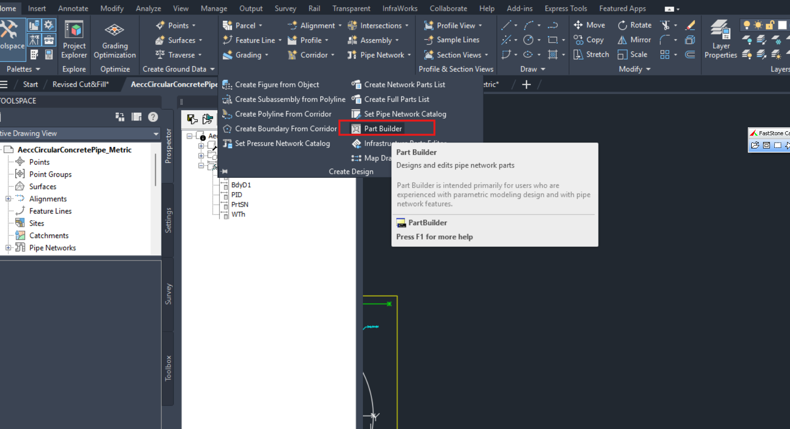
You can create new Gravity Part Size by using the Part Builder, and you can access it via Design->Parts Builder, as shown below
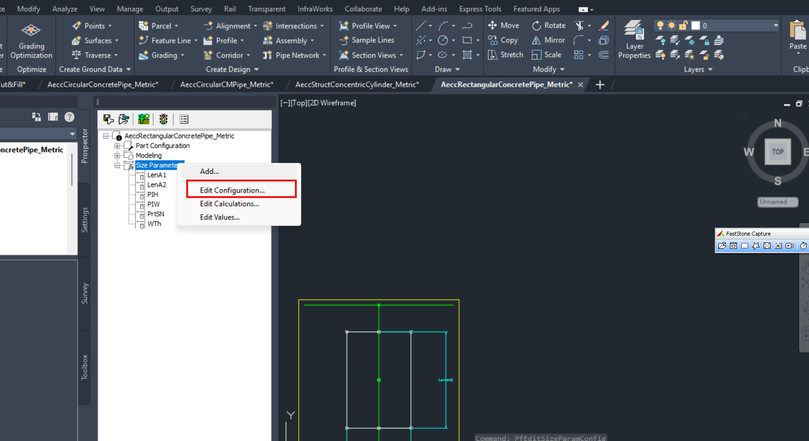
Then, you will be asked to select/create a Part Family, such as Concrete Pipe SI, in order to add a new size. To add a new size, you can just right click on the Size Parameters, Edit Configuration/Calculations/Values to add in new part sizes.
Pipe #
Roughly speaking, gravity pipe can be divided into 2 shape categories, the rectangle and the circular.
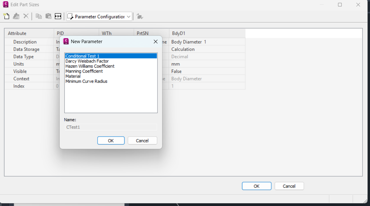
The critical dimensions that govern circular pipes are Pipe Inner Diameter (PID) and Wall Thickness (WTh). You can define them in Parameter Configurations by clicking on the white paper icon, as shown below
The critical dimensions that govern rectangle pipes are Pipe Inner Height (PIH), Pipe Inner Width (PIW) and Wall Thickness (WTh) correspondingly.
Take note for pipe, the outer dimension like Outer Diameter or Outer Width/Outer Length doesn’t by itself exist. So they can’t count as the dimensions provided by Part Catalogs
Circular or rectangle pipe? #
Inside the *.xml there is a CSS name section (SweptShape context section). There are 4 choices:
- SweptShape_Circular: PID will be read
- SweptShape_Rectangular: PIH/PIW will be read
- SweptShape_Elliptical: PIH/PIW will be read
- SweptShape_EggShaped: PIH/PIW will be read
So in this sense, all shapes saved for Circular shape are rectangle Pipes.
Structure #
Again, Structure can be roughly divided into two broad categories, the Cylinder and Cuboid.
The critical dimensions for Cylinder structure are Structure Diameter (SBSD) and Structure Height (SBSH).
The critical dimensions for Cuboid structure are Structure Height (SBSH), Structure Length (SBSL), Structure Width (SBSW).
Again, you can only define for the Diameter dimension or the Width/Length dimension, but not both.
Take note that in both cases,
- you can also define Wall Thickness (WTh), but that is not mandatory. It could be useful for rendering the structure, but it’s not that important to get the “actual sizes” of the structure
- For structure, Inner dimensions such as Inner Diameter aren’t strictly required, but I also see it define in some of the default Part Families shipped by Autodesk.
Cylindrical or box structure? #
Inside the *.xml there there is a SBS name section ( StructBoundingShape context section), which informs about what type of the pipe/structure it is:
- BoundingShape_Cylinder: Structure Diameter (SBSD) will be read
- BoundingShape_Box: Structure Length (SBSL) and Structure Width (SBSW) will be read.
Modelling consideration #
Civil 3D ships with quite a number of pipe/structure stock templates, that you can use by just adding the size of your own choice to the same topology model. This is the easiest way to get started on creating your own part catalogs.
If you are ambitious you can try to create your own topology model, by using Part Builder to create your own 2D or 3D model of the parts.
Pressure Part Catalog #
Add a new Part Size #
To add a new pressure pipe/fitting or appurtenance, you will need to use a separate program coming together with Civil 3D installation, the Content Catalog Editor (CCE).
Pipe #
There are a few parameters concerning pressure pipes that deserve some examinations
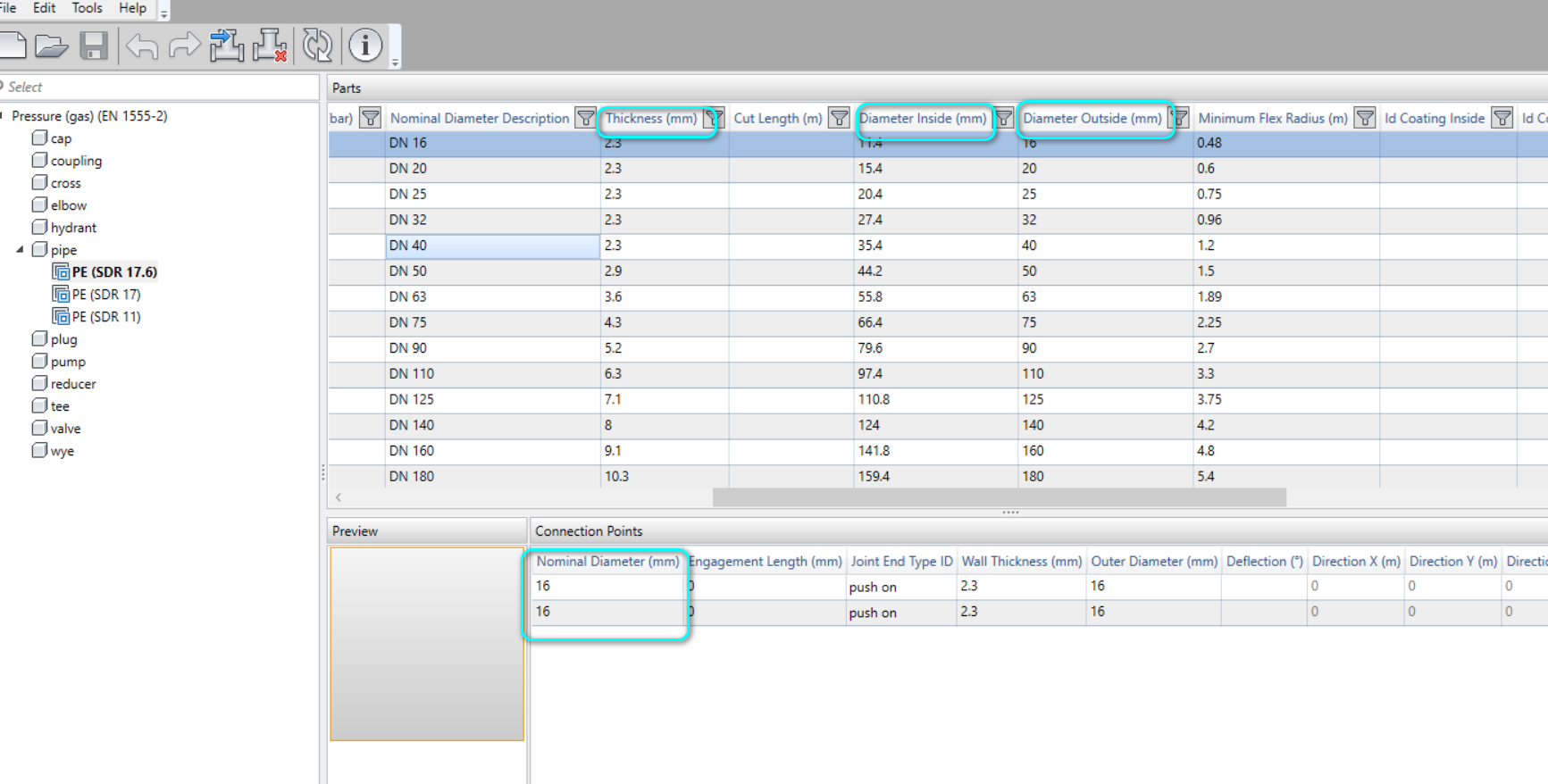
- Diameter Outside (mm)– the outside diameter. This is what Civil 3D will use to generate the outer profile of the pressure pipe
- Diameter Inside (mm) – the inner diameter
- Thickness (mm) – the pipe thickness. From what I understand, it doesn’t play directly into the rendering.
- Nominal Diameter (mm) – the nominal diameter of the opening, which the pipe has 2, and hence, two rows of nominal diameter as shown. Since the nominal diameter is on per opening basis, my guess is that they are useful only as design check and don’t feature in geometry generation. But I’m not really sure on this point
- Outer Diameter (mm) per opening – Astonishingly, each opening will have its own Outer Diameter! How is this diameter different from Diameter Outside, I don’t know. I can only guess that for pressure pipe, Diameter Outside ( on pipe basis) is being used, but Outer Diameter (on opening basis) is not.
Bottom line: to correctly model a pressure pipe in geometry, you will need to define Diameter Outside, Diameter Inside and “Thickness” correctly and consistently.
Fitting/Appurtenance #
Pressure pipe has 2 fix openings, but depending on the type of fitting or appurtenance, the number of opening can vary from 1 to 4. Given that Nominal Diameter and Outer Diameter are permanent fixtures of opening, I would have guessed that Outer Diameter and Wall Thickness would be used in rendering the geometry of Fitting/Appurtenance’s opening.
Also note that Nominal Diameter, Outer Diameter and Wall Thickness all seem to be independent of each other; there is no formula that link between them. Therefore, as a BIM modeler, you should ensure that all the numerical values are consistent and make sense physically.
Modelling consideration #
Modelling fitting and appurtenance are different than modelling pressure pipe. Whereas modelling pressure pipe is easy– you can just Import Part without a .content file, modelling fitting and appurtenance requires you to create a .content file, which you use PublishPartContent to create. It is quite a complicated process and requires you to create correct 3D solid model in AutoCAD prior to all this.
Different fitting size may require you to draw different 3D solid model in different DWG file due to the intricacy of the connections. This complexity is not seen in pipes or even gravity structure.

My passion is in sharing knowledge — Civil 3D or otherwise– with the world.
I’m also the benevolent dictator for life at MES Innovation Sdn Bhd.


