Offset Alignment #
The best way to understand Offset Alignment is as an alignment line that is “attached” to a Central Alignment. This means it will maintain the same distance from the Central Alignment throughout the stations, regardless of any changes made to the Central Alignment.
A use case for Offset Alignment is when you want to taper a road. You may want to target a subassembly to the Width or the Elevation of the Offset Alignment. However, I generally prefer to use Corridor Transition for this purpose.
To me, the real use case for Offset Alignment is when creating an intersection or junction between two Central Alignments. The Offset Alignment is very useful for defining the points where the junction starts and ends.
Connected Alignment #
The outer width of a Central Alignment at the chainage where the junction connects to it is the junction point. The outer width line itself can serve as the Offset Alignment. Each major and minor road has a junction connecting point, which serves as the start and end point of the Connected Alignment. To ensure continuity, the {x, y, z} coordinates at the connecting points must be the same for both the Offset Alignment and the Connected Alignment.
Why do we need a Connected Alignment for a junction? This is because the junction assembly—and hence the Corridor region—requires an alignment line to latch onto. The junction Connected Alignment delineates the left and right sides of the assembly.
Offset Profile #
An Offset Profile is simply the profile attached to the Offset Alignment. The easiest way to understand it is as the elevation of the Offset Alignment, defined by a certain percentage of slope. Essentially, the Offset Profile functions like the elevation line of the outer width of a road subassembly, such as the lane.
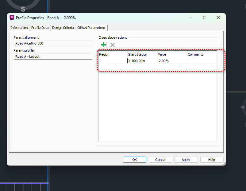
Civil 3D provides a handy way to define the Offset Profile, with the key parameter being the cross slope regions in the Offset Parameters, as shown below:
 .
.
With this definition, one can always ensure that the cross slope—measured from the Central Alignment to the Offset Alignment—remains -2% across all stations. At least you don’t have to define all the VIP, PVC, and PVT points repeatedly.


