Motivation #
This post explains how you can construct the road cross-section profile. It is written for those who want a visceral understanding of how Civil 3D constructs the 2D cross-sectional profile.
Cross Section Building Blocks #
Assembly #
Essentially, an assembly is the typical drawing of the road cross-section profile. This is the building block that we can control if we want to arrange our carriageway, shoulder, verge, or slope (daylight) according to our design.
Subassembly #
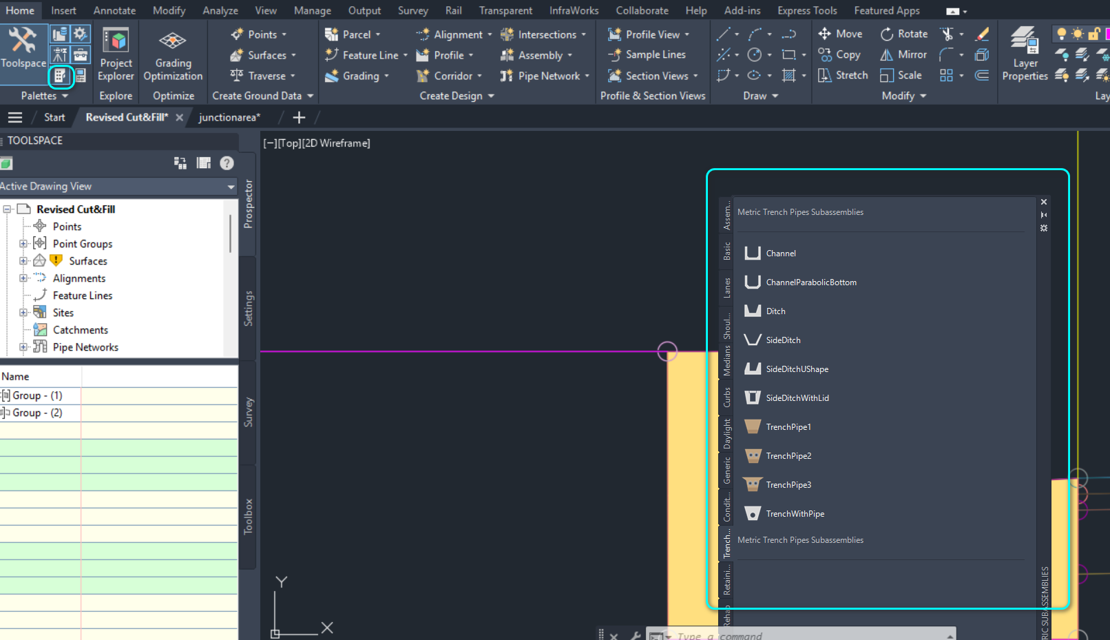
A subassembly is a single element that represents a “road width type”, such as carriageway, shoulder, etc. You can get the subassembly list from Home -> Palettes -> Tool Palettes. When you click on it, you will be presented with a floating, modeless window that will allow you to select your subassembly, as shown below.
Assembly Construction #
By chaining the subassemblies together, you can form your assembly. But the chaining process requires you to set the correct attachment point for each assembly, and this requires a bit of explanation.
It is simply not true that you can just place the subassembly at any location and the chaining will work — no, you will have to ensure that the two subassemblies share a common point, as highlighted below.
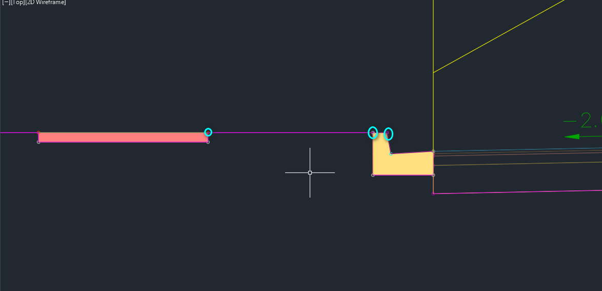
You can’t simply drag a subassembly near another and expect them to join — they won’t. You can’t even ensure they share the same edge and expect them to join — they won’t. The only way to ensure it works is to select your subassembly, mouse over one of the points of the subassembly until the circle around it lights up, and only then click on it to join.
How to Model: #
Drop #
To model drop, you will have to use a specific subassembly called LinkVertical. This allows you to connect to your existing subassembly at one end, and at the other end, specify how far down you want your next subassembly to be.
Then the other end of the LinkVertical can be used to connect to the start of another subassembly.
Slopes #
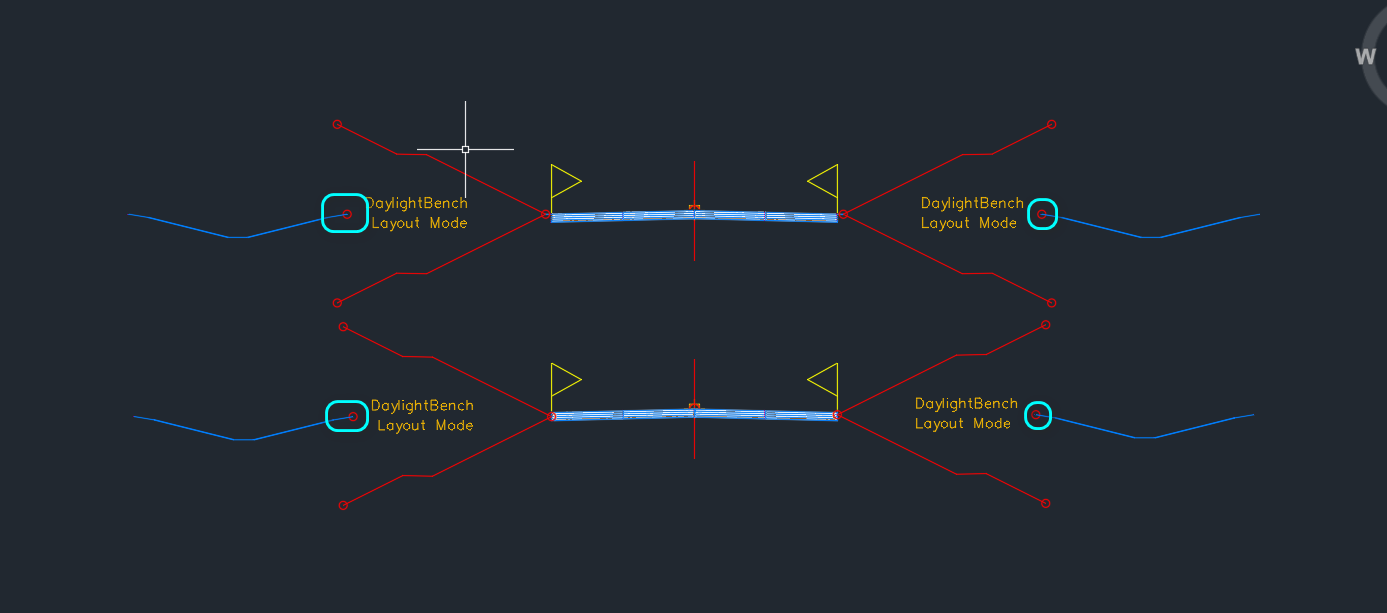
For unknown reasons, slope is called Daylight. There are quite a number of Daylight subassembly templates that you can use, such as DaylightBench.
Usually, DaylightBench has to be used together with ConditionalCutOrFill, which allows you to specify different configurations depending on whether your slope is a Cut or Fill slope.
Ditch After the Daylight #
To model a ditch (or any other subassembly), you will have to ensure that the ditch is connected to the center point of the daylight, as shown below:
That point is pretty much the only point you can connect to for Daylight subassembly.

My passion is in sharing knowledge — Civil 3D or otherwise– with the world.
I’m also the benevolent dictator for life at MES Innovation Sdn Bhd.


