Motivation #
AutoCAD comes with a built-in template for Plan and Profile Production, usually located at:
%AppData%\Local\Autodesk\C3D 20xx\enu\Template\Plan Production
The default template file is named Civil 3D (Metric) Plan and Profile.dwt. However, it includes only three layouts, each corresponding to a specific scale: 1:100, 1:500, and 1:5000.
This guide is for those who want to create additional layouts with different scales. Since scale and viewports are tied together (a smaller scale means more viewports are needed to cover the entire road length), the number of viewports will be automatically adjusted based on the selected scale.
Create or Duplicate a New DWT Template File #
The first step is to duplicate the default Civil 3D (Metric) Plan and Profile.dwt file and rename it to Scale50.dwt, indicating that the layout will use a 1:50 scale for your project.
Create a New Layout #
In the Scale50.dwt file, duplicate an existing layout:
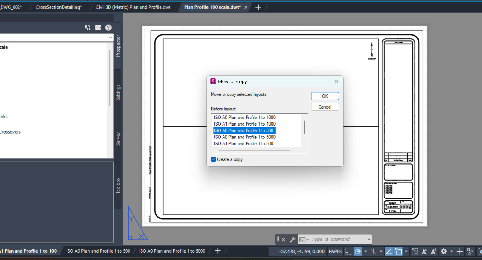
Rename the duplicated layout to:
ISO A0 Plan and Profile 1 to 50
Save the modified DWT template file.
Change the Scale #
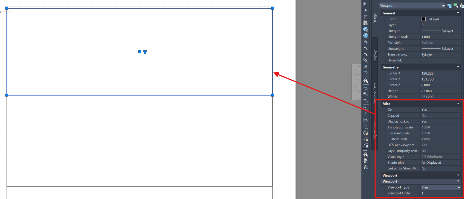
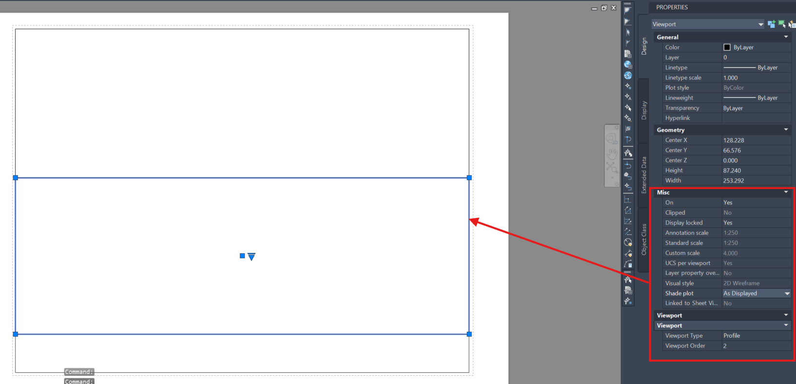
To configure the layout scale, click on the viewports. In the image above, there are two viewports:
- Top — Plan view
- Bottom — Profile view
To change their respective scales:
- Set Display Locked to No
- Adjust the numerical scale accordingly
Apply It to an Actual Drawing #
Your new template, Scale50.dwt, is now ready to be applied to your drawing.
- Go to Output → Create View Frames
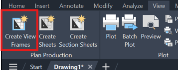
- In the Sheet section, select the
Scale50.dwtfile - You’ll find the new layout you just created is now available for selection — choose it
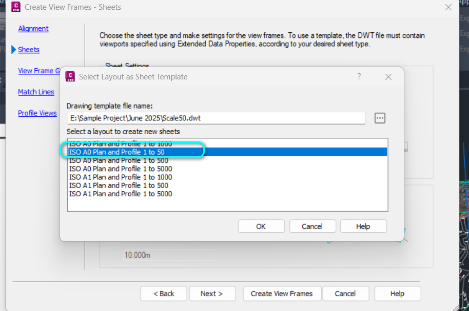
- After that, click on Output → Create Sheets to generate the new layouts.
- You’ll see that the layout is indeed set up with the new 1:50 scale.


