In Civil 3D there are a few ways to configure the appearances of your entity: layers, Styles, Set Styles. The unfortunate thing about them is that they do overlap sometimes, which results in unnecessary confusion: why is it that my change doesn’t reflect at all?
The purpose of this document is to explain the concepts in some details, so that one would know exactly what configuration to edit.
Layers #
Layer is the most basic properties of an AutoCAD entity. Note that this is an CAD entity– it’s not a Civil 3D entity ( civil entity), which means that you are only changing the appearances of the CAD entities like Lines, Arcs and not wholly the appearances of the civil entities, like Road Alignment, Sample Lines.
A layer is just a grouping of different properties, such as Color. All the CAD entities that have the same layers will usually have the same properties, unless you choose to override it at entity level. This is important as you would want the appearance of a same group entities to change at once, instead of changing them one by one.
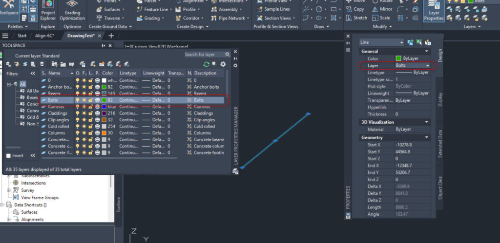
In the image above, the line has “Bolts” as layer, and hence, all of the visual properties for the Line like Color, Transparency and all will follow whatever that is specified in the “Bolts” layer, unless they are individually overriden.
Styles #
CAD entities by itself has no civil meaning. You have lines and polyfaces, but that’s not drains ( gravity pipes) or sump ( structure). To make it into a gravity pipe ( a civil object) you need to have other properties that are of interest to civil engineers, such as Invert Level, and all the relevant CAD entities must appear as a logical whole entity. This is where Styles come in.
Styles operate on a higher plan than Layers, it applies on civil objects rather than on CAD objects. Because a civil object contain multiple different CAD objects, therefore we can have different Component Types for a single style, and each Component Types can refer to the same or different layer.
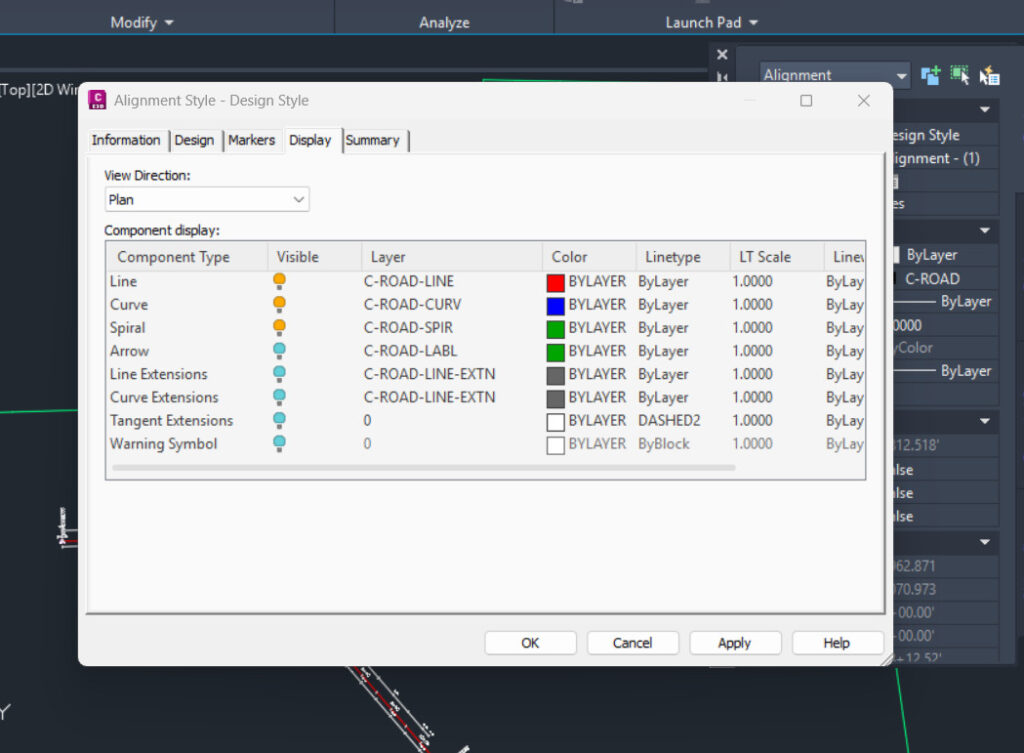
Take for example, Alignment Styles have a Display tab, which host multiple Component Types such as Line, Curve, Spiral and so on. And take note from the figure below that Line Extensions and Curve Extensions have exactly the same layer, namely “C-Road-LINE-EXTIN”. However, they could have different Color despite that the Color property is defined in layer.
So an Alignment Style will affect the display of an Alignment entity, and the corresponding CAD entities in the Alignment civil entity will appear differently, according to how you define the Component Type in the Style.
A style can also contain other custom properties that are not easily categorized by layers, such as Table settings and text styles.
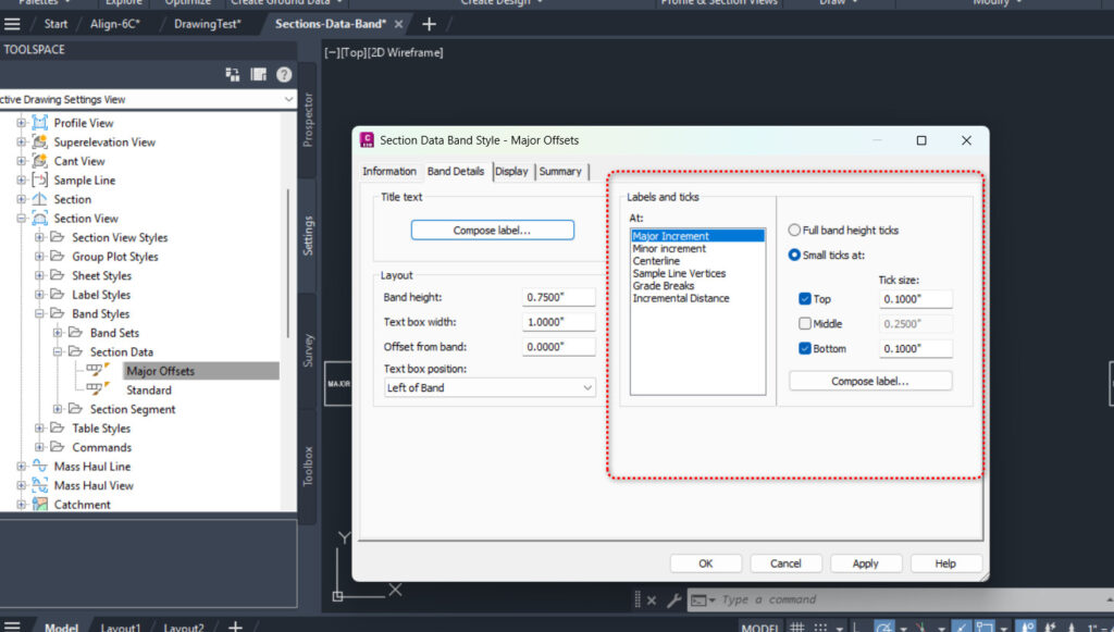
Take for example, referring to Section Data Band Styles under Section View in the Settings tab of the ToolSpace palette, in addition to the Display tab that we are already familiar with from the above, we have an extra tab, “Band Details” that govern how a band looks. The Band Details tab will contain more options such as Major Increment option, Minor Increment option, and so on, that will customize on how should a band– which is just a row in the table looks on the screen.
Set Styles #
Next we turn our attention to Set Styles. The name here it’s important: it means A Set of Styles, which should give you a rough idea of what it’s for. Some examples will be helpful here.
Band Set Styles #
Band Set Styles are used in profile views and section views to control the display of bands. So a Band Set style is just a collection of Band Styles, each governs the appearances of a separate band ( table row).
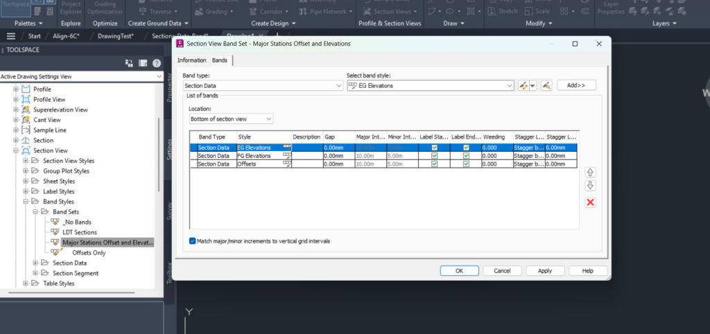
Take for example, let’s look at Major Stations Offset and Elevations Band Set Style for Section View. It contains 3 Styles stacked on top of each other in the Section View:
- EG Elevation Band Style, this is a band style that will show the Existing Ground (EG) elevation across a section view.
- FG Elevation Band Style, this is a band style that will show the FinishingGround (FG) elevation across a section view.
- Offsets Band Style, this is a band style that will show the offset value across a section view.
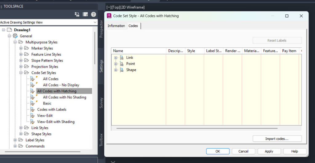
Code Set Styles #
Code Set Styles are used to govern the appearance of a corridor— a 3D civil object that shows itself in plan view and section view ( assembly view). A corridor is a complicated object with multifaceted appearance depending on you are looking it from the plane or section view, and with multiple components– such as assembly, subassembly, to maintain the consistency regardless of what assembly you use, there is a need to subdivide them into Point, Links and Shapes, and assign appropriate styles to control for them.
Take for example, the Pave1 Shape code. All the Shape that are assigned with this Code will have exactly the same appearances, because they will have exactly the same Style ( which governs the lines) and Label Style ( which governs the texts).
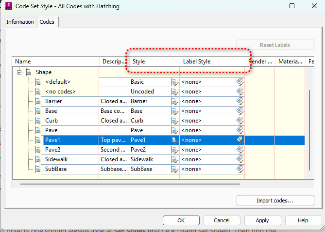
So as long as your subassembly’s Shape code is Pave1, then regardless of what it actually is ( it could be GenericPavementStructure, or LaneSuperelevationAOR, or BasicShoulder), they will show up all the same.
This is just another way of enforcing consistency, not unlike layers in AutoCAD.
You can roughly imagine the Pave1 Shape code is a style, and all the Point, Links and Shapes Code are a set of styles, and hence the name Code Set Styles.
Label Set Styles #
Another example that we can look at is the Label Set Styles. For the example below, the Label Sets All Labels have 5 type of styles. These 5 types of styles will be applied in different scenario, with different styles.

The individual style ( such as “Parallel with Tick”) can be found also under “Label Styles” subfolder, in this case, it’s “Station->Major Station”.
In the event that there is no style defined as per below:

No label will get shown. Do take note that this is a valid Label Set Style also.
Navigation Rules of thumb #
As a rule, when working with civil objects one should always look at Set Styles first ( e.g.: Band Set Styles), if it is available. Then find the corresponding Style that you want to work on ( e.g.: a table row), and then zoom in to individual AutoCAD entities to work on the layer. This is the hierarchy that you should keep in mind when you are doing Civil 3D Appearance editing.

My passion is in sharing knowledge — Civil 3D or otherwise– with the world.
I’m also the benevolent dictator for life at MES Innovation Sdn Bhd.


