Disclaimer #
This article is intended for educational purposes only and assumes you are working with legally obtained Autodesk software and catalogs. It’s not an endorsement to actually edit the Network Catalog or DWGs without Civil 3D and it’s accompanying tools.
No Autodesk files are redistributed.
Motivation #
You can edit Pressure Part Sizes—such as Pressure Pipe, Fitting, or Appurtenance—via the Content Catalog Editor (CCE), but this requires the installation of Civil 3D. The motivation for this post is to show how to edit (add/remove/modify) Pressure Part Sizes without using the Content Catalog Editor, i.e., with no Civil 3D installed.
I’ve written a post exploring how to edit Gravity Part Sizes without using the tool of the day, Part Builder. Interested readers can consult here.
Content Catalog Editor (CCE) #
Content Catalog Editor is a standalone program (EXE) that comes with the installation of Civil 3D, but it is completely independent. It is located in the %AutoCAD%\C3D\ folder, so presumably it shares some underlying DLLs with Civil 3D. This is the usual tool for editing the pressure network catalog.
Tutorials for CCE abound, so I won’t cover them here. You can refer to the official documentation to get started.
Edit Part Catalog without CCE #
The *.sqlite file #
Unlike the gravity network catalog, where part size information is stored in .apc and .xml files, the equivalent information for the pressure network is stored in a .sqlite file. For fittings and appurtenances, additional information is stored in a .dwg file and a .png file.
Let’s start with the .sqlite file. It is usually located in this folder:
C:\ProgramData\Autodesk\C3D 20XX\enu\Pressure Pipes Catalog\Metric\
If you are working on Imperial unit you will just have to look into
C:\ProgramData\Autodesk\C3D 20XX\enu\Pressure Pipes Catalog\Imperial\
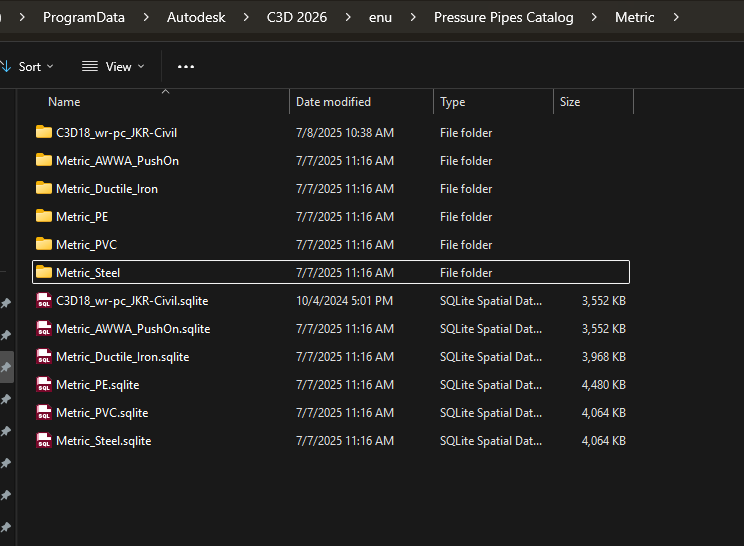
By default, Autodesk ships a few Pressure Part catalogs, such as Metric_AWWA_PushOn.sqlite, Metric_ISO_K.sqlite, etc. Pretty much everything in the screenshot below, except for C3D18_wr-pc_JKR-Civil.sqlite.
Editing the pressure pipe size #
To edit a pressure pipe size, simply modify the related Part Catalog’s .sqlite file. You don’t necessarily need to use CCE. Since tutorials for using CCE are widely available, I’ll focus on how to edit it using a free software, DB Browser for SQLite, because it is just a standard .sqlite file.
First, open the file in DB Browser. It might look daunting (or not) depending on your familiarity with database schemas. You’ll see a list of tables (there are 44 of them as of the C3D 2026 version!).
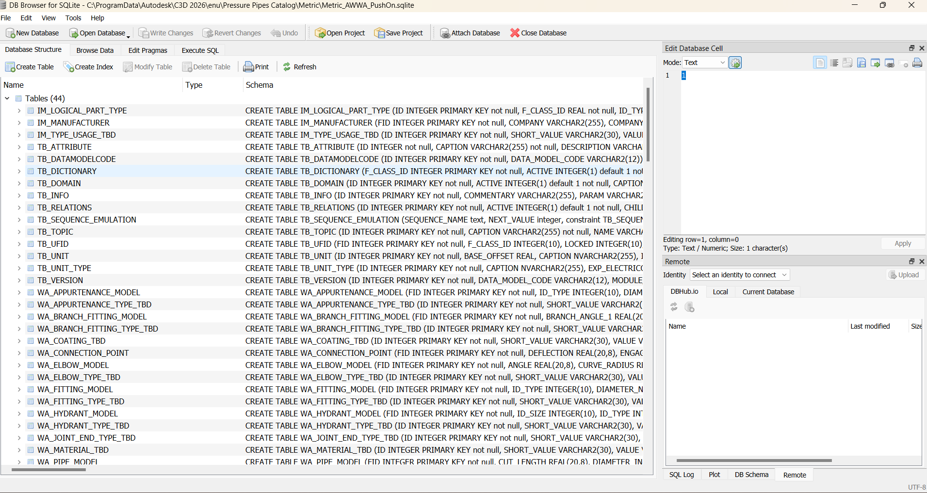
But you can safely ignore most of them. For pressure pipes, the important table is WA_PIPE_MODEL under the Browse Data tab:
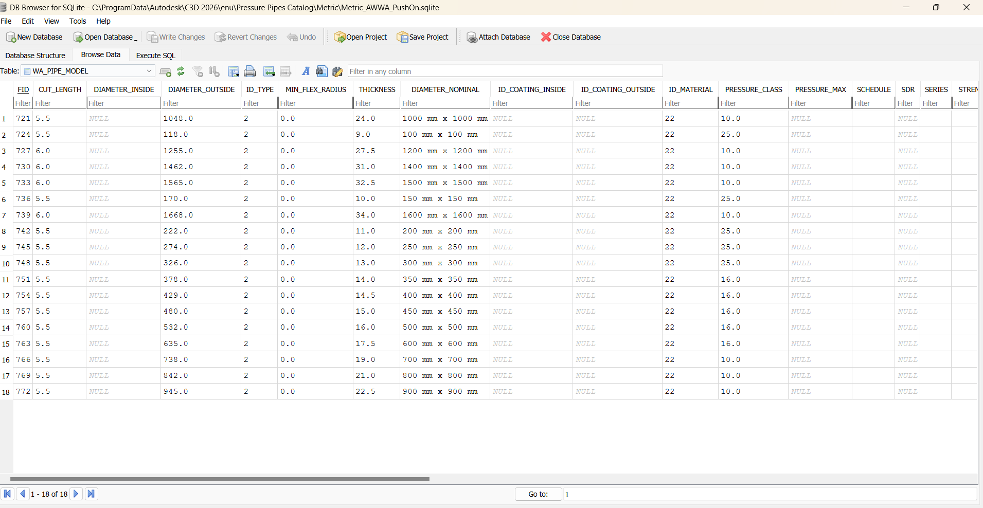
Setting aside the issue of some essential fields (like DIAMETER_INSIDE) being not well defined, you can verify—by comparing the columns with those in CCE—that these really are the critical properties a pipe size should have.
To edit them, just input the appropriate values. That’s it—you’ve updated the pressure pipe properties, including its size! It’s your responsibility to ensure the data are internally consistent (e.g., outer diameter = inner diameter + 2×thickness), but I assume you already know that.
Part Family ID, Part Family Name, and PID columns #
What about the Part Family ID and PID columns, as shown below?
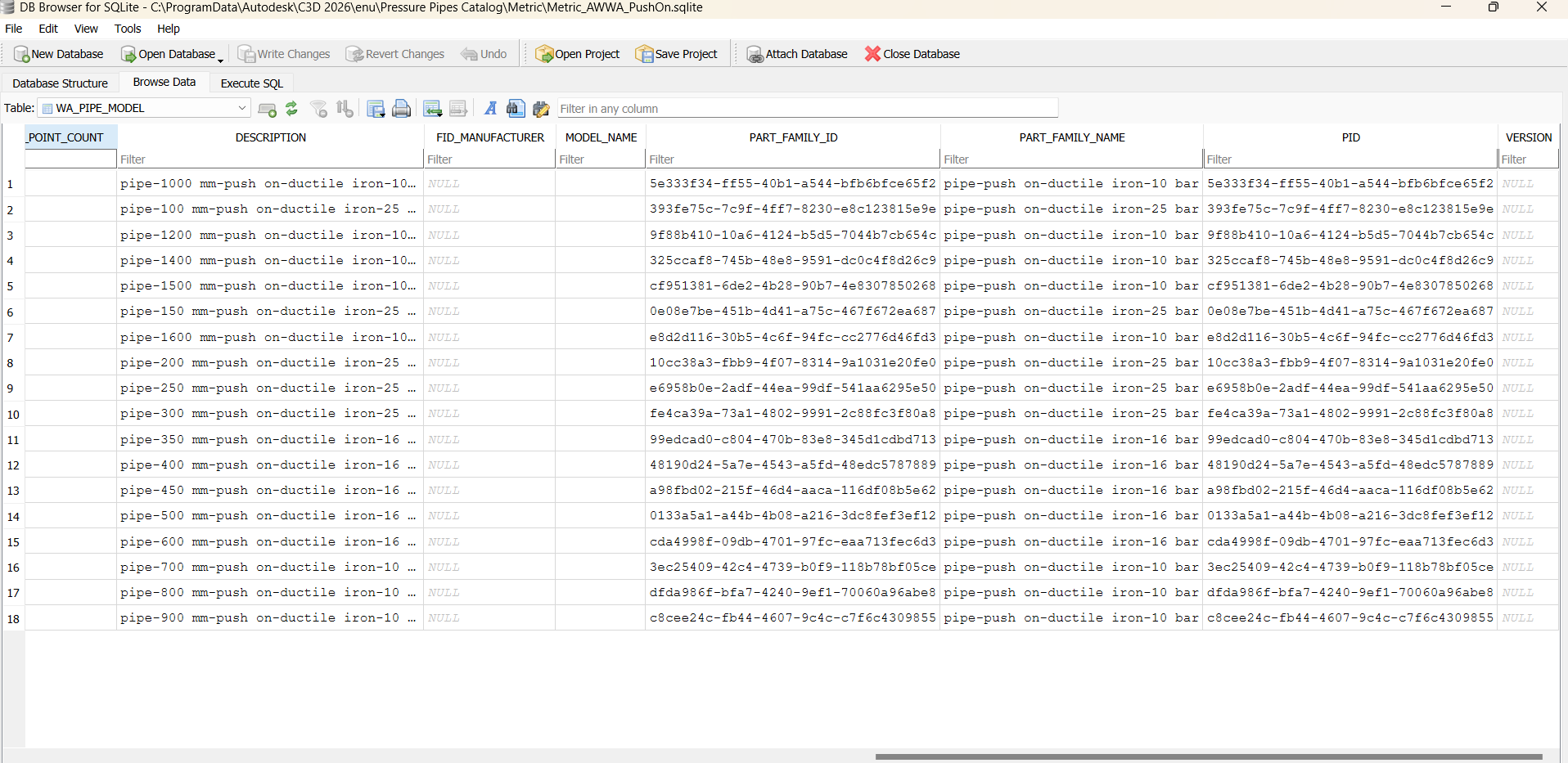
They look intimidating—any 128-bit GUID will! But the underlying logic is simple.
The Part Family ID is a GUID representing the entire Part Family—a set of similar part sizes—while the PID is the GUID of a specific part size. The PID must be unique for each Pipe Size. Ideally, one Part Family should have only one Part Family ID.In practice, this isn’t always strictly enforced, because even the same Part Family can have multiple Part Family ID– Civil 3D allows for some flexibility.
However, the relationship between Part Family ID and PID must always be a one to many relationship.
For pipes, these columns are relevant only as far as the Connection Points (openings) are concerned. Pipes have 2 Connection Points. Inside the WA_CONNECTION_POINT there is a PID column that links to the relevant row ( Part Size) in the WA_PIPE_MODEL. So each row in WA_CONNECTION_POINT corresponds to one Connection Point setting, which links back to a specific Part Size.
These two columns play more role in Fitting/Appurtenance section, we will come to that again later.
As for the Part Family Name column, it can be anything, but for consistency, one Part Family ID must always have exactly the same Part Family Name.
Editing the Fitting/Appurtenance #
The .sqlite file contains more tables for different types of fittings/appurtenances, such as WA_ELBOW_MODEL, WA_HYDRANT_MODEL, WA_APPURTENANCE_MODEL, and so on.
Like pressure pipes, you can change the values directly using DB Browser or your own SQLite editor. However, unlike pressure pipes, the Part Family ID and PID columns are now important—we’ll discuss why shortly.
Because these columns matter, you can’t simply add a new row if you want to create a new fitting/appurtenance size.
The *.dwg and *.png files #
These files are used for defining new fittings/appurtenances. Here’s how they relate to the Part Family ID and PID columns.
Here’s how Civil 3D handles this when inserting a fitting or appurtenance:
- Civil 3D reads the Part Family ID, then searches the subfolder (e.g.,
Metric_AWWA_PushOn\DWG). - It looks for a DWG file with the same name as the Part Family ID.
- It opens that DWG file and finds a block with the same name as the PID.
- It inserts that block into the drawing.
The screenshot below shows a DWG file, a PID block, and the matching Elbow entry in the database—all matching up.
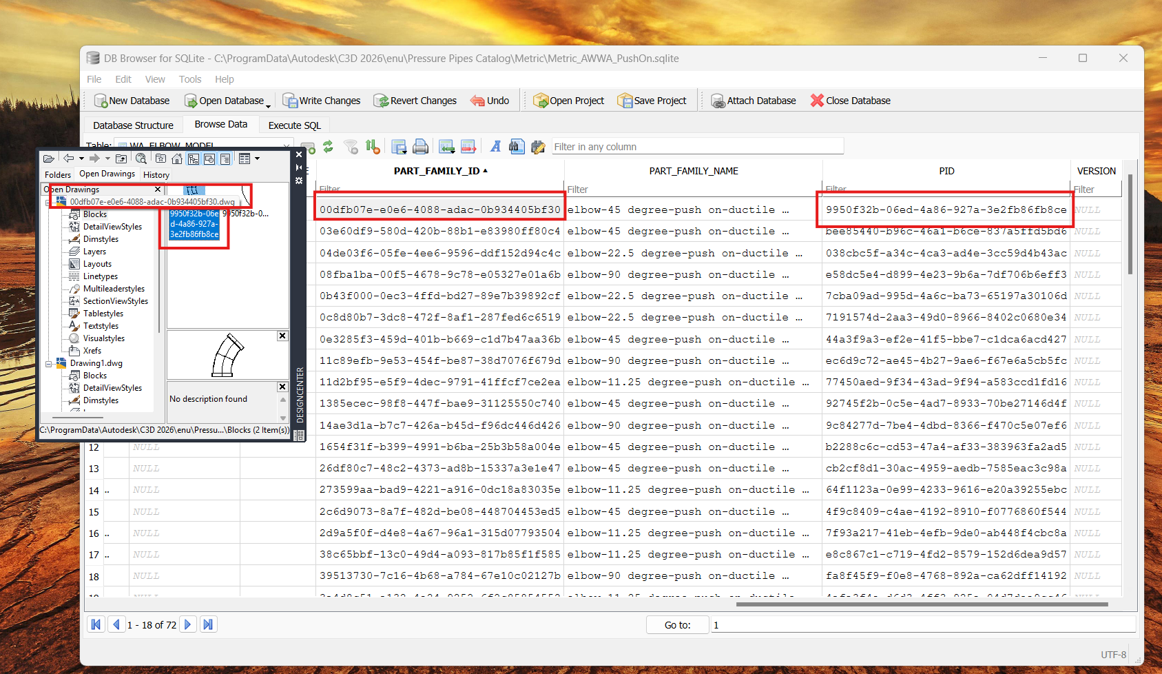
Fittings and appurtenances often have complex geometry, even when they look visually similar. That’s why Civil 3D needs DWG “block” drawings for fittings/appurtenances but not for pressure pipes. Pipes are just simple hollow cylinders and don’t need block drawings—thus, no need for the Part Family ID and PID columns.
The API #
You can get the Part Family ID and the PID via the code, namely PressurePartSize.FamilyGuid and PressurePartSize.PartSizeGuid
Create new Pressure Pipe Size #
To add a new Pressure Pipe Size, you will have to add a new entry to WA_PIPE_MODEL and its corresponding connection properties in WA_CONNECTION_POINT. Note that the FID is a unique identifier across all pipes, fittings, appurtenance and connection point. There is a table that generates a FID for you, TB_UFID table. Here’s the procedure:
- Go to TB_UFID table, create a new row, and get a new FID, this is your FID for your new pressure part size, to be used in WA_PIPE_MODEL. The F_CLASS_ID is the class ID of the pressure pipe type, which value can be found in the IM_LOGICAL_PART_TYPE.
- Then insert the row in WA_PIPE_MODEL, along with other pressure part size properties.
- Create two entries in TB_UFID table for the use of connection points and obtain their respective FID. For Connection Point the F_CLASS_ID is 12.
- Then insert these two entries into the WA_CONNECTION_POINT table with the above FID, together with the PID corresponding to the pressure part size, along with other connection point properties.
Create new Fitting/Appurtenance sizes or Part Types? #
Creating new Fitting/Appurtenance sizes or new part types is complex. First, create 3D solids, then use the PublishPartContent command in Civil 3D to convert the solids—along with settings—into a .content file, then import it into CCE.
You can create solids in vanilla AutoCAD, but what about the necessary settings to make it a valid Part Size? From my sleuthing, it seems the settings are stored inside the XData of the AutoCAD block. If you can script or use another CAD program, you might be able to inspect the XData and figure out the required settings.
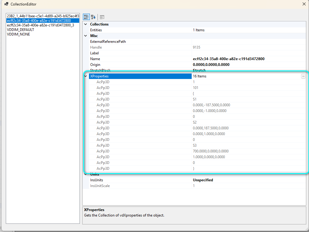
So yes, it does seem very probable to create a Part Size or Part Type using just vanilla AutoCAD (with some simple scripting), though I haven’t try it yet.
What about the .png file? #
Simple—take a screenshot and put it in the appropriate folder. Done.
Add Materials for Parts #
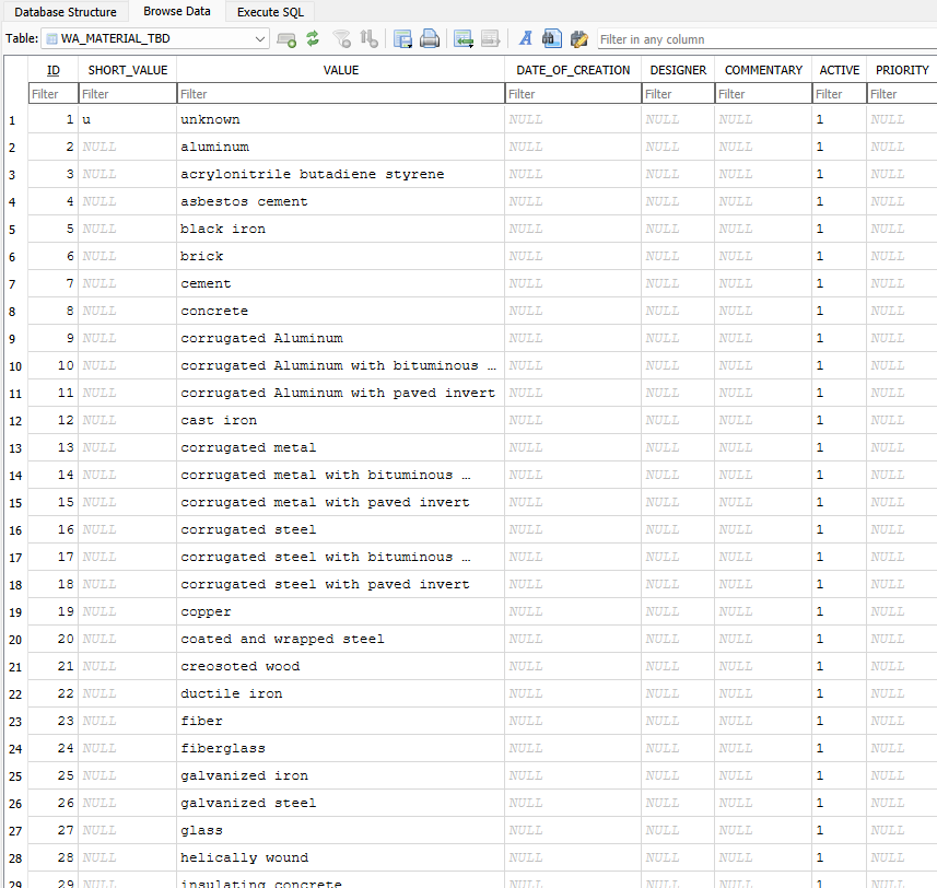
This is somewhat related. CCE does not let you add your own material because the Id Material column only offers a dropdown.
But with DB Browser, you can! Look for the WA_Material_TBD table and add your own material row, complete with ID, value and all that. You’ll then be able to select the new material in CCE, or manually input the ID for your parts.
