
Disclaimer #
This article is intended for educational purposes only and assumes you are working with legally obtained Autodesk software and catalogs. It’s not an endorsement to actually edit the Network Catalog or DWGs without Civil 3D and it’s accompanying tools.
No Autodesk files are redistributed.
Motivation #
This is written for those who want to understand in depth how the Part Size in the Gravity Part Catalog is linked to the Part Size you see in the drawing, and how you can add/edit/remove sizes by just editing XML files in Notepad++, without using the Part Builder.
Hacking the Part Catalog in Notepad++ #
If you want to create new shapes for pipes or structures, Part Builder is the way to go. But if you already have existing Part Catalogs and Part Families, and all you want is to add sizes or modify the relationship between different variables, you don’t need Part Builder—or even Civil 3D—at all. You can use Notepad++ or any XML editor to do it.
You only need to know how to link the Part Family to the correct XML file, and you’re good to go.
The *.apc file #
In the example below:
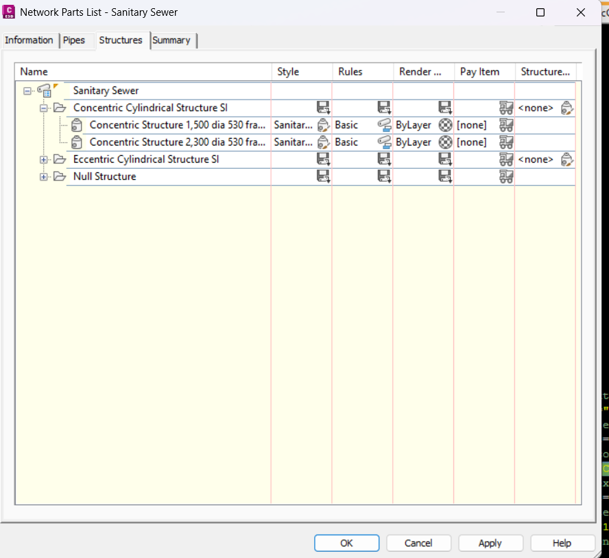
The Part Family is something like “Concentric Cylindrical Structure SI” or “Eccentric Cylindrical Structure SI.” It’s essentially a list of same-shaped Part Sizes with different dimensions.
Internally, the Part Family is identified by a context called Catalog_PartID. This Catalog_PartID links the Part Family name like “Concentric Cylindrical Structure SI” to the correct XML files, via an intermediate file: the .apc file.
Here’s a more descriptive example. Recall that the default current part catalog is set to the following directory:
C:\ProgramData\Autodesk\C3D 2024\enu\Pipes Catalog\
And we set the Pipe Catalog and Structure Catalog to the respective catalog: Metric Pipe Catalog and Metric Structure Catalog.
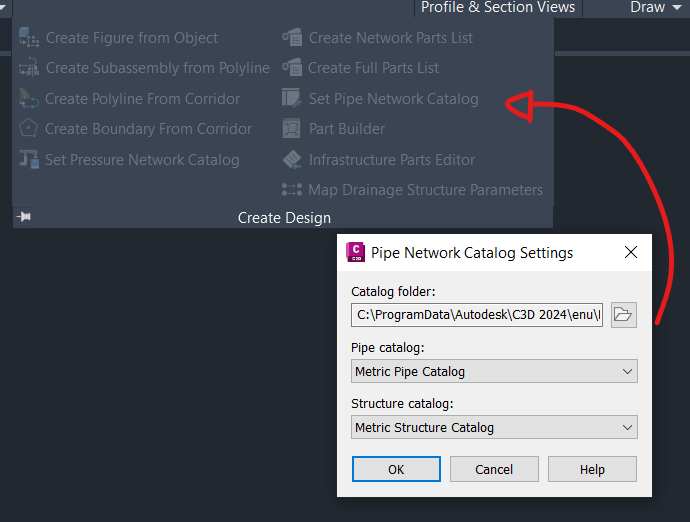
- You can navigate to the
C:\ProgramData\Autodesk\C3D 2024\enu\Pipes Catalog\Metric Structures\folder and find yourself a Metric Structures.apc file. - Then you can open up the file in Notepad++, and look for the exact string “Concentric Cylindrical Structure SI.”
- That “Concentric Cylindrical Structure SI” is nested under a
PartXML section with a specific ID. In my case, the ID is “F4657229-FA05-4718-9B1A-9230101749E6.” - Importantly, if you are accessing it via the .NET API, this ID is the PartFamily.GUID. This simply means that you can trace the Part Size properties definition in XML from all the way from Part Catalog, as long as you know the registry location of the Part Catalog, as an alternative to whatever is exposed by the Civil 3D .NET API.
- Inside the .apc file, you will also find the link to the
AeccStructConcentricCylinder_Metric.xmlfile, which is where the different Part Sizes for “Concentric Cylindrical Structure SI” are stored.
The Aecc*.xml file #
The Aecc*.xml** file stores all the configurations for the part sizes. Again, this file is editable in Notepad++ or any XML editor.
Open it up in your favorite editor and you can verify that the Catalog_PartID is still the same, namely “F4657229-FA05-4718-9B1A-9230101749E6.”
This is how it looks like ( some definitions are omitted for brevity):
<?xml version="1.0"?>
<LandPart desc="Part Table" version="1.0" xmlns:xlink="http://www.w3.org/1999/xlink" fixColumn="C1">
	<ColumnConstView desc="Parameter-driven Display" id="CCV1" viewKey="3d" viewName="AeccPartRecipe" pathsRelativeTo="Table">
		<Images>
			<Image>
				<URL xlink:title="Part Reference Image" xlink:href="AeccStructConcentricCylinder_Metric.bmp"/>
			</Image>
		</Images>
		<Recipe>AeccStructConcentricCylinder_Metric.dwg</Recipe>
	</ColumnConstView>

	<ColumnConstList desc="Inner Structure Diameter" dataType="float" unit="mm" name="SID" id="CCL1" visible="1" context="StructInnerDiameter" index="0">
		<Item id="i0">1200.0000</Item>
		<Item id="i1">1350.0000</Item>
		<Item id="i2">1500.0000</Item>
		<Item id="i3">1800.0000</Item>
		<Item id="i4">2050.0000</Item>
		<Item id="i5">2300.0000</Item>
		<Item id="i6">2550.0000</Item>
	</ColumnConstList>

	<ColumnConstList desc="Wall Thickness" dataType="float" unit="mm" name="WTh" id="CCL3" visible="1" context="WallThickness" index="0">
		<Item id="i0">125.0000</Item>
		<Item id="i1">150.0000</Item>
		<Item id="i2">170.0000</Item>
		<Item id="i3">200.0000</Item>
	</ColumnConstList>

	<ColumnConstList desc="Floor Thickness" dataType="float" unit="mm" name="FTh" id="CCL4" visible="1" context="FloorThickness" index="0">
		<Item id="i0">150.0000</Item>
		<Item id="i1">170.0000</Item>
		<Item id="i2">200.0000</Item>
		<Item id="i3">250.0000</Item>
	</ColumnConstList>

	<ColumnConst desc="Part Name" dataType="string" unit="" name="PrtNm" id="CC3" visible="0" context="Catalog_PartName" index="0">AeccStructConcentricCylinder_Metric</ColumnConst>
	<ColumnConst desc="Part Description" dataType="string" unit="" name="PrtD" id="CC4" visible="1" context="Catalog_PartDesc" index="0">Concentric Cylindrical Structure SI</ColumnConst>
	<ColumnConst desc="Part ID" dataType="string" unit="" name="PrtID" id="CC5" visible="0" context="Catalog_PartID" index="0">F4657229-FA05-4718-9B1A-9230101749E6</ColumnConst>

	<ColumnCalc desc="Structure Diameter" dataType="float" unit="mm" name="SBSD" id="CCA6" visible="1" context="StructDiameter" index="0">$SID + (2.0 * $WTh)</ColumnCalc>
	<ColumnCalc desc="Structure Height" dataType="float" unit="mm" name="SBSH" id="CCA7" visible="1" context="StructHeight" index="0">$SRS + $FTh</ColumnCalc>
	<ColumnCalc desc="Vertical Pipe Clearance" dataType="float" unit="mm" name="SVPC" id="CCA8" visible="1" context="StructVertPipeClearance" index="0">$SFH + $SCH + $SBPC</ColumnCalc>
	<ColumnCalc desc="Workplane Offset 1" dataType="float" unit="mm" name="WPOf1" id="CCA9" visible="1" context="Geometry_WorkplaneOffset" index="1">$SFH</ColumnCalc>
	<ColumnCalc desc="Workplane Offset 2" dataType="float" unit="mm" name="WPOf2" id="CCA10" visible="1" context="Geometry_WorkplaneOffset" index="2">$SFH + $SCH</ColumnCalc>
</LandPart>
You can easily verify that the above definition corresponds to what you see in the Part Builder.
So, adding a new size is merely a matter of adding a new entry in the XML file. Similarly, deleting a size is just a matter of removing an entry.
Likewise, Civil 3D allows you to express the relationship between two properties as an equation in the XML file (e.g., SBSH = $SRS + $FTh). You can just as easily alter the expression in the XML file.
What about the *Pipe_Metric.xml? #
One might notice that for pipe XML files, there is a peculiar section called Primary Key at the top, which contains many rows with unique identifiers (UUIDs). They are typically represented as 32-character hexadecimal strings, often displayed with hyphens separating certain groups of characters. Something like this:
	<ColumnUnique desc="Primary Key" datatype="string" name="UUID" visible="0">
		<RowUnique id="r0">1815E08D-5B6A-42B0-8711-3F4839A38301</RowUnique>
		<RowUnique id="r1">8AEAAAC3-CFFE-4D85-B964-03680E46A993</RowUnique>
		<RowUnique id="r2">9651A85A-17F5-40F6-B50E-0887D25D5F7A</RowUnique>
		<RowUnique id="r3">493FA146-5743-4F5F-81BB-E4D06B51B08A</RowUnique>
	</ColumnUnique>
Again, to add a new Part Size, you have to add a corresponding row to every size-dependent XML section. The new row needs a valid, globally unique UUID. Once a size has been distributed or used in drawings, preserve its UUID: generating a different one for the same size changes its catalogue identity. A repeatable generator should therefore reuse existing UUIDs and create a new UUID only for a genuinely new size.
What about the same-name .bmp and .dwg files? #
The part XML explicitly references both assets:
- The
.dwgis the Part Builder recipe containing the compatible topology and parameter-driven geometry. - The
.bmpis the family reference image shown by catalogue and Part Builder interfaces.
When a new material family uses the same basic topology as an existing family, it can be scaffolded by cloning a compatible recipe and image. For example, a circular VCP family can reuse a compatible circular-pipe recipe while its own XML supplies the family identity, size UUIDs, PID, wall thickness, display names, and references to its renamed .dwg and .bmp assets.
This method does not automatically create a detailed socket or joint model. It retains the cloned recipe’s topology. Use Part Builder when the new family requires different constraints, parameters, or geometry.
A repeatable family-generation workflow #
For a template-compatible circular pipe family, the complete workflow is:
- Select an existing recipe whose topology and required parameters are compatible.
- Assign one stable Part Family ID and register the family in the
.apcfile. - Create the family XML and keep its
Catalog_PartIDidentical to the.apcPart ID. - Add matching rows for DN, PID, WTh, and every other size-dependent column.
- Give every size a valid, unique, and stable UUID.
- Clone the compatible
.dwgrecipe and.bmpreference image, then update the XML and APC references to their new names. - Validate matching row counts, unique IDs, referenced files, and successful loading in Civil 3D.
XML validation can catch catalogue-structure errors, but it does not replace opening the family in Civil 3D and checking its displayed dimensions and behaviour.
Conclusion #
You don’t need Civil 3D merely to inspect eligible Part Sizes or to add and remove XML rows. You can also scaffold a new Part Family without Part Builder when it safely reuses an existing compatible recipe. Part Builder remains the appropriate tool for creating or changing the topology and parameter-driven geometry, and Civil 3D should be used to validate the resulting family before distribution.

My passion is in sharing knowledge — Civil 3D or otherwise– with the world.
I’m also the benevolent dictator for life at MES Innovation Sdn Bhd.


