Motivation #
Civil 3D surfaces cannot contain points that share the same {x,y} coordinate but have different z values. In other words, only one point can exist at a given {x,y} location. This limitation makes it difficult to model surfaces with vertical drops.
The closest workaround, when you want to represent a wall where two elevations meet at the same location, is to create a “smear” region—an almost unnoticeable transition where the elevation changes gradually over a very short distance in plan view.
Civil 3D provides a tool for this, called a Wall Breakline, which is just one type of breakline. Breaklines are line constraints that prevent TIN triangles from crossing them. The triangles must be either fully inside or outside the breakline, never straddling it.
This guide explains how wall breaklines work, since Autodesk’s documentation does not make the concept very clear.
Creating base polylines #
Suppose we want to create a surface with two flat areas:
- On the left, a 2 × 2 m square at elevation 45 m.
- On the right, a 2 × 2 m square at elevation 42 m.
From this geometry, we know there is a 3 m vertical drop from left (45 m) to right (42 m).
First, create a 3D Polyline (3DPoly) and a Polyline (Pline) that will serve as the basis for the breaklines. Assign elevations to them as shown below:
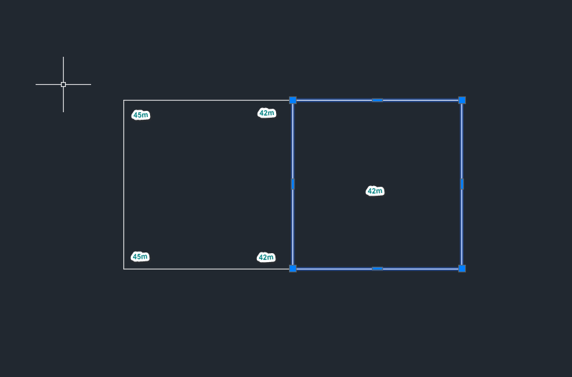
Notice that the left-hand 3DPoly has different elevations at its ends (45 m on the left, 42 m on the right). The right-hand Pline, however, is flat at 42 m.
Also note: these elevations are not the final surface elevations. The left-hand side should ultimately be 45 m, but along the edge that connects to the Pline, its polyline is set to 42 m. As a rule, the base polylines should use the lowest elevation where they meet.
Creating breaklines #
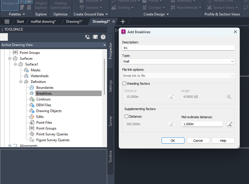
Next, create a Surface.
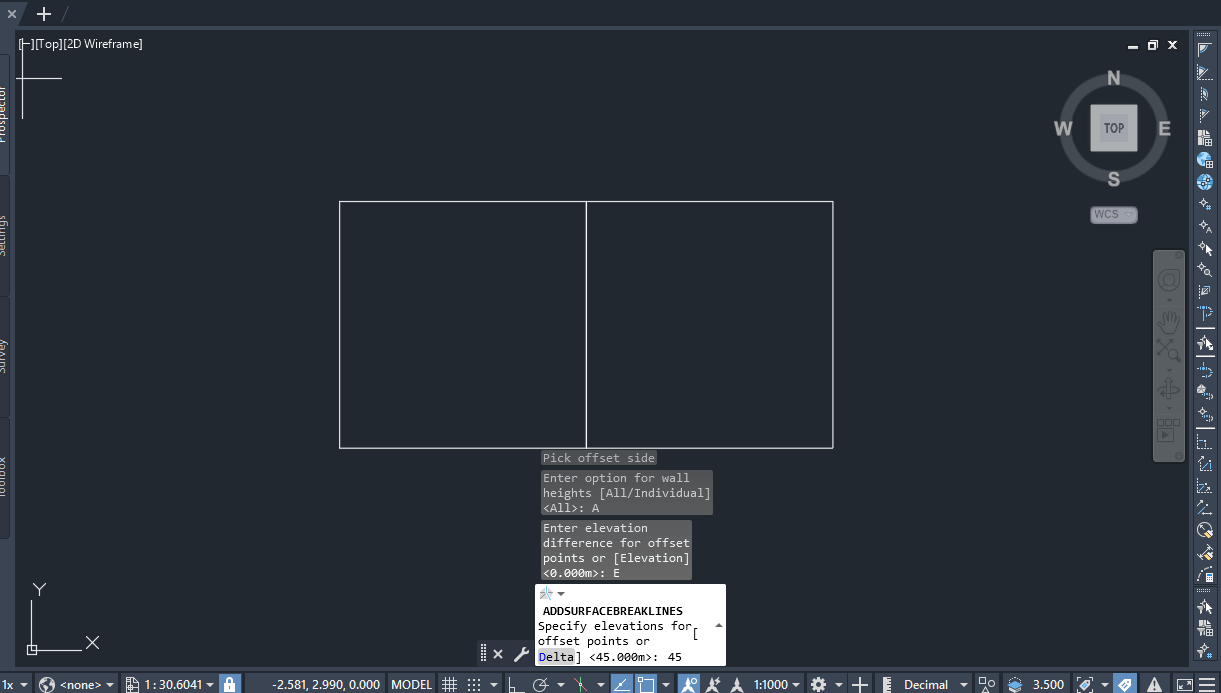
Then add a wall breakline by selecting the left-hand 3D Polyline (we’ll call it b1), as shown below:
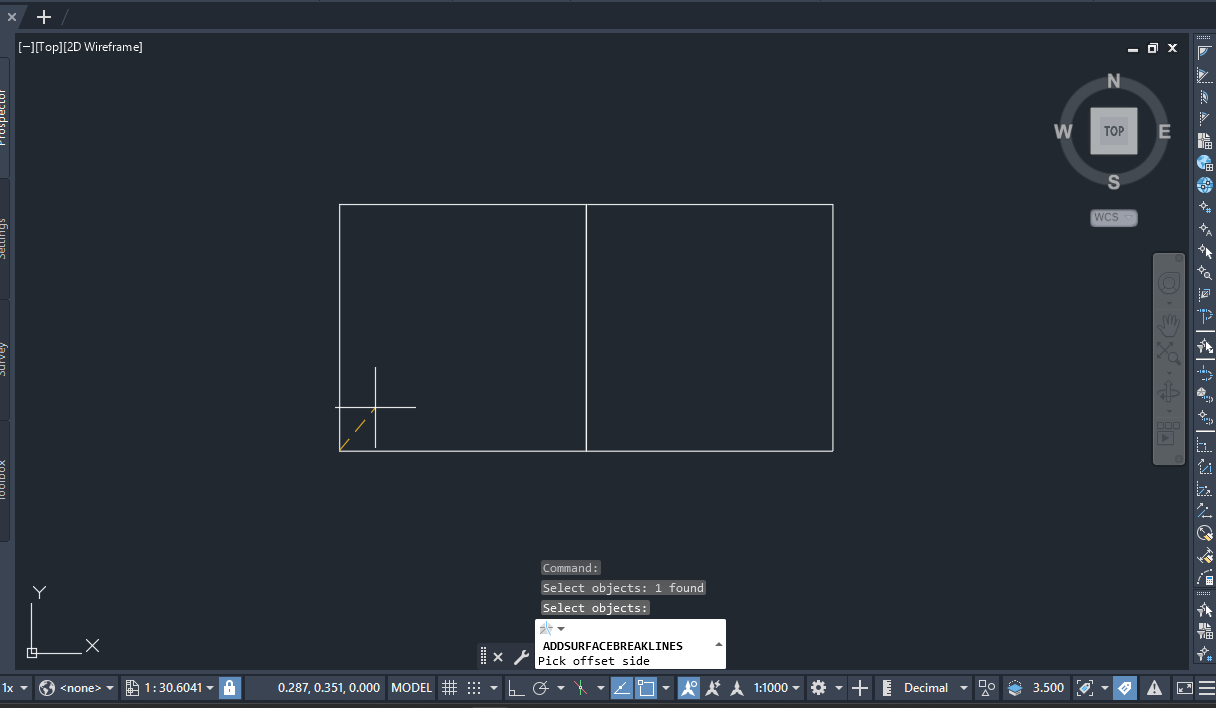
You’ll also need to choose the offset direction. Always pick the direction pointing inward—toward the inside of the polygon—not outward:
Setting breakline elevations #
Because we want the surface on the left-hand side to be at 45 m, set the offset point elevations to 45 m:
Here’s what happens under the hood:
- Civil 3D starts with the elevations of the original
3DPoly. - It then connects those to the offset points, which form a slightly smaller polygon inside the polyline.
At the shared edge between the 3DPoly (42 m) and the Pline (42 m), Civil 3D smoothly transitions the elevation up to 45 m at the offset points.
This change happens over a very short distance (sometimes less than a millimeter), which creates the appearance of a vertical wall. But it is not a true vertical face.
When you look at the breakline properties, you’ll see that unfortunately, elevations from the base polyline, not the final surface elevations:
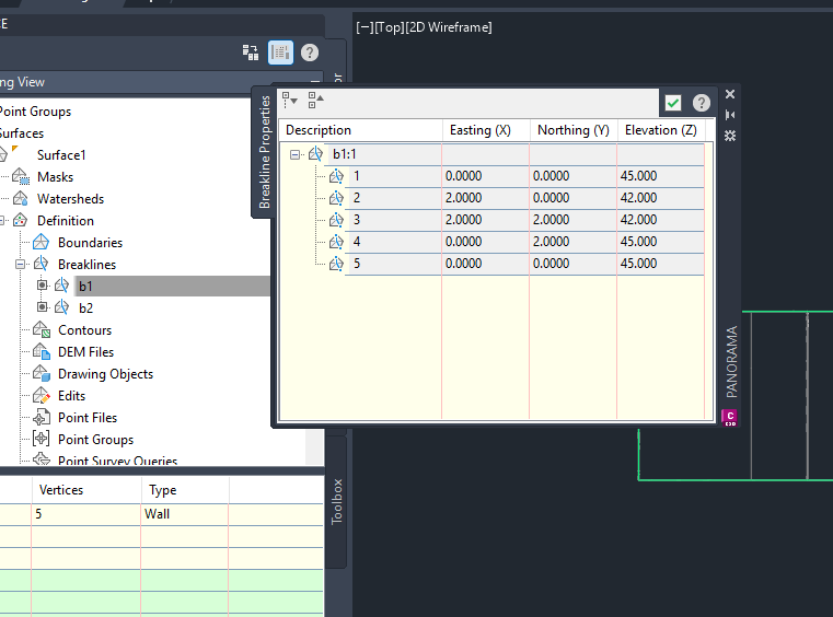
This causes a lot of confusion because I was expecting to see the actual elevations concerning the surface and not it’s scaffolding. Until Autodesk improves the feature, you may need scripts to display the actual breakline elevations.
Adding the second breakline #
Repeat the same process for the second breakline:
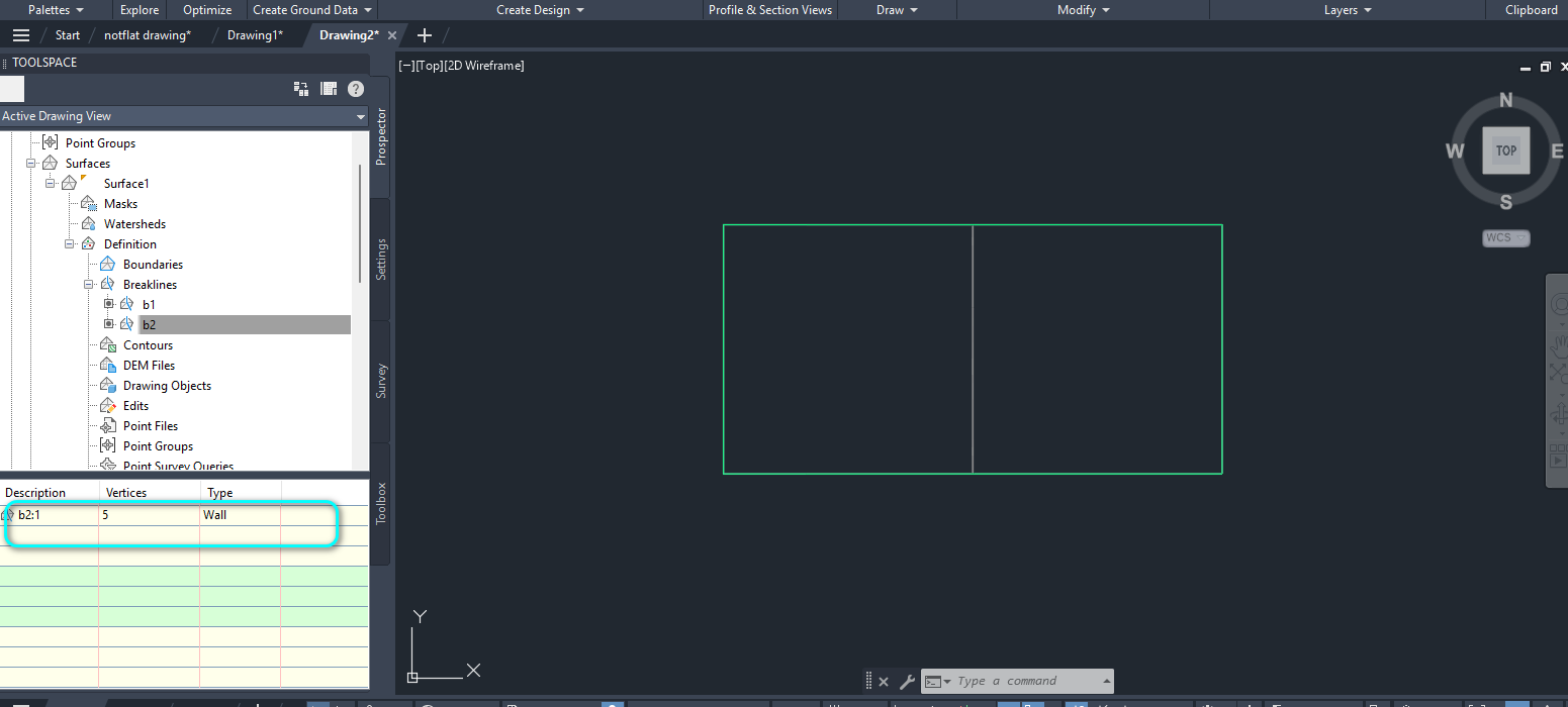
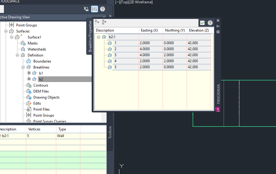
Here are the properties:
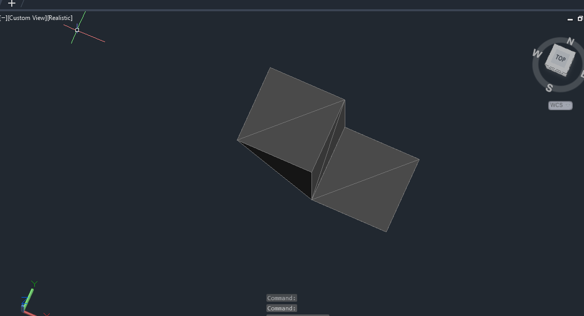
3D view and verification #
To confirm everything is correct, select all the entities and view them in Object Viewer. Rotate the model to see how the elements fit together:

My passion is in sharing knowledge — Civil 3D or otherwise– with the world.
I’m also the benevolent dictator for life at MES Innovation Sdn Bhd.


