
Vertical Profile & Its Role in Road Design #
A Profile is much more than just a simple 2D line drawn across the Profile View (the grid or graph) in Civil 3D. It is the vertical backbone of your road -if the horizontal alignment shows you the road stretch going left or right across the terrain, the vertical profile will show how your road ascends or descends against the terrain.
In Civil 3D road design, the vertical profile is is required for creating the corridor surface. Without a profile, the design lacks road elevation information, making it impossible for road software to determine the assemblies’ vertical positions at every point along the road.

Components of the Vertical Profile #
There are a few geometrical components of the profile that we need to understand to ensure a smooth vertical transition of the road.
Detailed explanation can be referred here
How Do We Create The Road Vertical Profile in Civil 3D? #
Step 1: Horizontal Alignment #
Create the horizontal alignment (Centerline) for the road.
This step is a must as the profile is the sub-object of the alignment -the software will prompt users to select the alignment when we try to create the profile later on.
Steps:
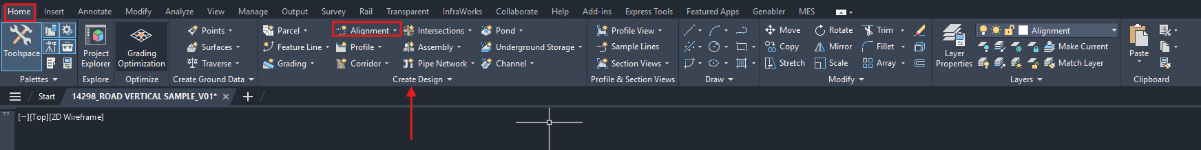
- Go to Home tab > Under the Create Design section, click on Alignment > Select Alignment Creation Tools.
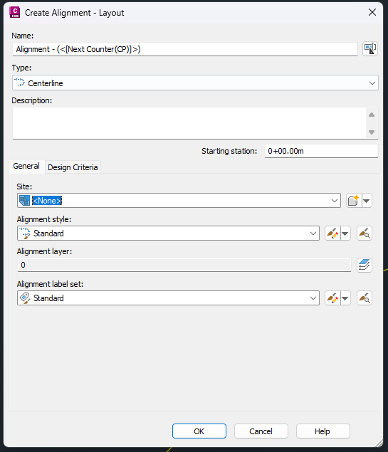
- Set the Name, Type, General Settings, and Design Criteria to apply to the alignment > Click OK.
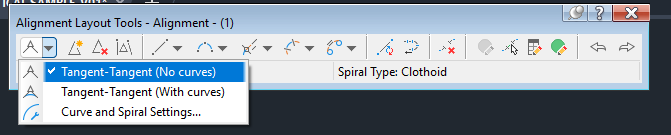
- In the Alignment Layout Tools dialog, select the command for Tangent-Tangent (no curves) > Lay out the IP (Intersection Point) to create the tangents along the road.
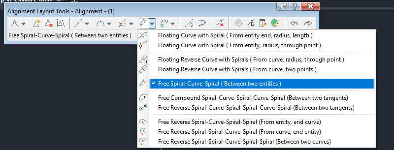
- For horizontal curves, select the command Add Free Spiral-Curve-Spiral (Between Two Entities) > Select the tangent before and after the IP > Set the radis and spiral length according to your design.
Step 2: Create Surface Profile #
For this section, the drawing must contain the surface for the Existing Ground.
Steps:
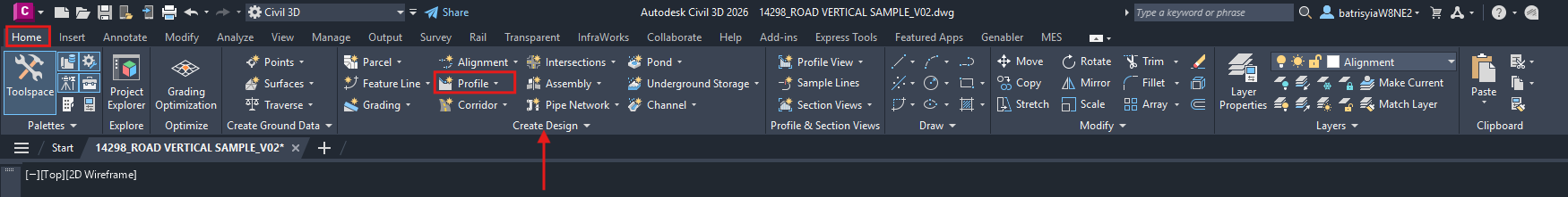
- Go to Home Tab > Under the Create Design section, click on Profile > Select Create Surface Profile.
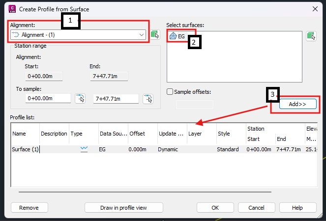
- Under the Create Profile for Surface dialog, select the correct Alignment from the dropdown > Select Surface representing the existing ground > Click on the ‘Add>>’ button. The surface will be listed under the Profile List.
-
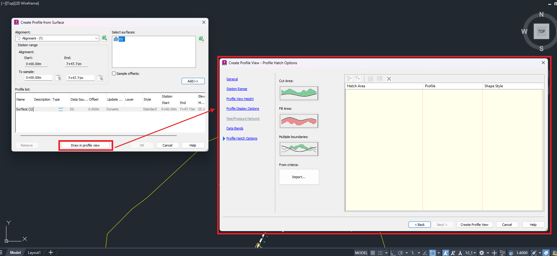
Click the ‘Draw in profile view’ button > The software will display the Create Profile View – General dialog > Set the following parameters accordingly:
a. General
b. Station Range
c. Profile View Height
d. Profile Display options
e. Data Bands
f. Profile Hatch Options
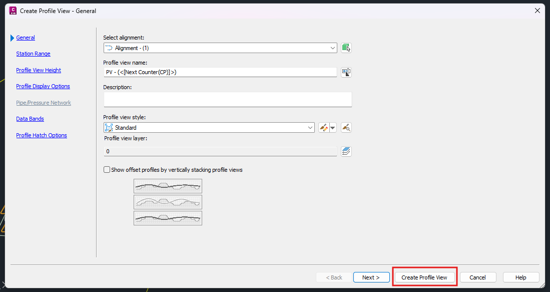
- Click on the ‘Create Profile View’ button > The software will prompt users to set the origin for the profile view (placement of the profile view grids in your drawing)
Step 3: Drawing The Road Profile Line #
- Go to Home tab > Ubder the Create Design section, click on Profile > Select the Profile Creation Tools.
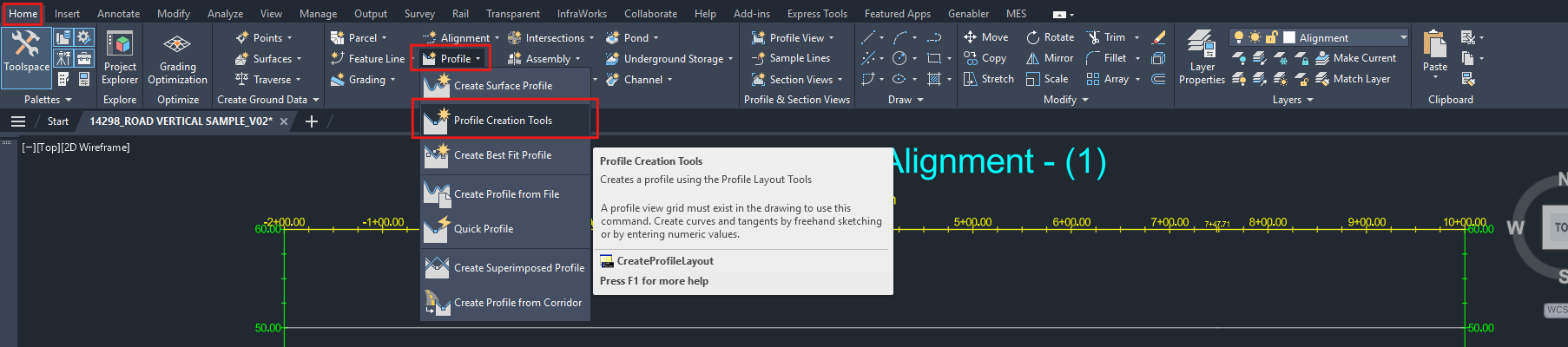
-
The software will prompt the user to select the Profile View (Graph/Grid) that contains the surface profile created in Step 2: Create Profile Surface View above.
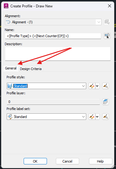
-
Create Profile – Draw New dialog will appear > Properly set the General and Design Criteria parameters to be applied to the profile > Click OK
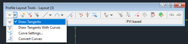
- Under the Profile Layout Tools, select the Draw Tangents Without Curve function to lay out the PVI (Points of Vertical Intersection) along the road, this creating the tangents for the curves.
- Select Draw Free Vertical Curve (Parabola) function > Select the first tangent, followed by the second tangent from the profile line drawn in (4).
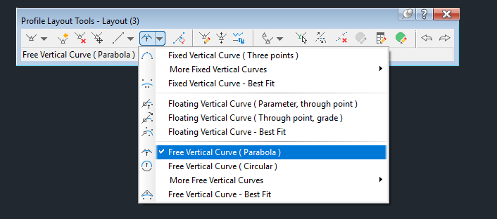
- Software will prompt to input the Radius/Length/Passthrough/K value > Choose K value or Radius > Input the value as per your design (You can adjust these parameters later on)
How Do We Adjust The Parameters of The Crests or Sags? #
For the profile line drawn in Step 3: Drawing the Road Profile Line, we may need to adjust the parameters such as the elevation, curve radius, or the K values. To do so,
- Select the Profile Line drawn on the Profile View > Click on the Geometry Editor under the Modify Profile section > The software will open up the Profile Layout Tools dialog.
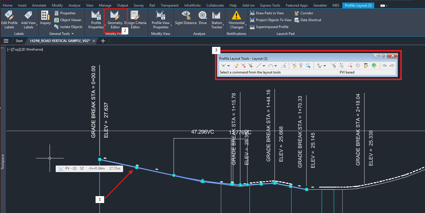
- Click on the Select PVI function > The software will open up the Profile Layout Parameter dialog > Click on the PVI that requires adjustments on the parameters. The Profile Layout Parameters will display the related parameters.
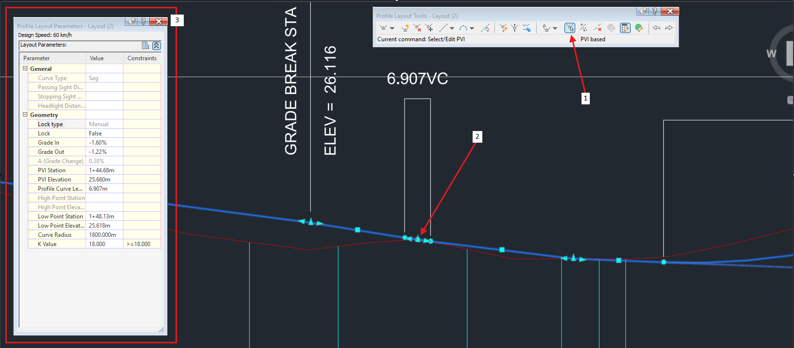
- Made changes to the parameters accordingly. Press Enter, and the Profile Line drawn will be updated.
Transitioning Curve to A Grade Break Where K Equals 0 #
In scenarios where road standards are not required, such as when designing a small internal road with minimal elevation changes, it is acceptable to set the K values to 0. This results in no vertical curves at the PVI, creating a sharp but small dip or hump relative to the terrain.
In Civil 3D, when K equals to 0, the PVI is defined as a grade break. Hence, attempting to adjust the K value for the crests or sags to 0 will trigger an out-of-range error, as in the image below.
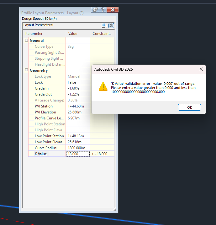
Since Civil 3D requires K values for the crests and sags to be greater than 0, this constraint must be overcome by changing the line type from a curve to a grade break.
Steps: #
- Select the Profile Line > Under the Modify Profile section, click on Geometry Editor.
- On the Profile Layout Tools dialog, click on the Profile Grid View function to open up the Profile Entities dialog > Select the PVI that should be converted to a grade break. The PVI will be highlighted on the drawing.
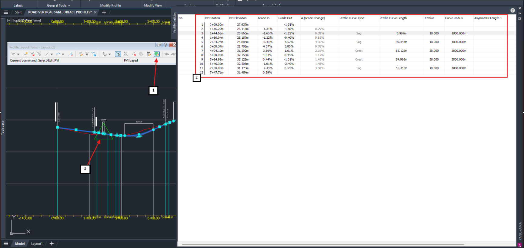
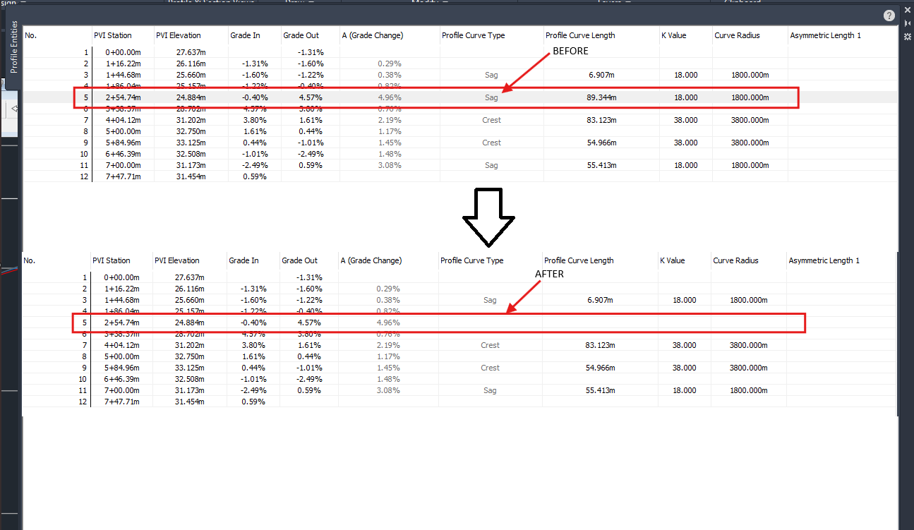
- Click on the Delete Entity function under the Profile Layout Tools dialog > Select the crest or sag of the PVI selected in (2).
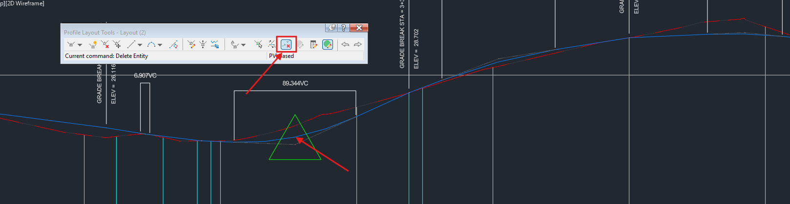
- Under the Profile Entities, the PVI will no longer be of a crest or a sag, and the K value is automatically considered as 0.

My passion is in sharing knowledge — Civil 3D or otherwise– with the world.
I’m also the benevolent dictator for life at MES Innovation Sdn Bhd.


